---
title: How to wire the GateLIFT barrier hardware (electrician guide)
description: Step-by-step guide for electricians wiring Ronspot's GateLIFT barrier hardware — the Shelly Pro 2 relay and CSL 4G router — onto a car-park barrier.
---
[Skip to content](https://help.ronspot.co/gatelift-barrier-wiring-electrician-guide#main-content)
[Open support ticket](https://help.ronspot.co/kb-tickets/new?hsLang=en) [Track my tickets](https://ronspot.co/customer-portal?hsLang=en)
[](https://ronspotflexwork.com/)
- [Platform](https://ronspotflexwork.com/platform/)
Show submenu for Platform
- [Parking Management System](https://ronspotflexwork.com/office-parking-management/)
- [Desk Booking System](https://ronspotflexwork.com/desk-booking-system/)
- [Meeting Room Booking System](https://ronspotflexwork.com/meeting-room-booking-system/)
- [Workplace Analytics](https://ronspotflexwork.com/workplace-analytics/)
- [Integrations](https://ronspotflexwork.com/integrations/)
- Solutions
Show submenu for Solutions
- [Employee Experience](https://ronspotflexwork.com/employee-experience/)
- [Workplace Operations](https://ronspotflexwork.com/workplace-operations/)
- [Space Planning](https://ronspotflexwork.com/space-management/)
- [Customer Case Studies](https://ronspotflexwork.com/case-studies/)
- [Pricing](https://ronspotflexwork.com/pricing/)
- Resources
Show submenu for Resources
- [Help Centre](https://help.ronspot.co/)
- [Product Updates](https://ronspotflexwork.com/feature-releases/)
- [System Status](https://ronspotflexwork.com/system-status/)
- [Contact](https://ronspotflexwork.com/contact-us/)
Open main navigation
Close main navigation
- [Platform](https://ronspotflexwork.com/platform/)
Show submenu for Platform
- [Parking Management System](https://ronspotflexwork.com/office-parking-management/)
- [Desk Booking System](https://ronspotflexwork.com/desk-booking-system/)
- [Meeting Room Booking System](https://ronspotflexwork.com/meeting-room-booking-system/)
- [Workplace Analytics](https://ronspotflexwork.com/workplace-analytics/)
- [Integrations](https://ronspotflexwork.com/integrations/)
- Solutions
Show submenu for Solutions
- [Employee Experience](https://ronspotflexwork.com/employee-experience/)
- [Workplace Operations](https://ronspotflexwork.com/workplace-operations/)
- [Space Planning](https://ronspotflexwork.com/space-management/)
- [Customer Case Studies](https://ronspotflexwork.com/case-studies/)
- [Pricing](https://ronspotflexwork.com/pricing/)
- Resources
Show submenu for Resources
- [Help Centre](https://help.ronspot.co/)
- [Product Updates](https://ronspotflexwork.com/feature-releases/)
- [System Status](https://ronspotflexwork.com/system-status/)
- [Contact](https://ronspotflexwork.com/contact-us/)
- [Open support ticket](https://help.ronspot.co/kb-tickets/new)
- [Track my tickets](https://ronspot.co/customer-portal)
- [Book a Demo](https://ronspotflexwork.com/book-a-demo/)
[Book a Demo](https://ronspotflexwork.com/book-a-demo/)
Need help with Ronspot?
- There are no suggestions because the search field is empty.
1. [Help Centre](https://help.ronspot.co/?hsLang=en)
2. [Integrations](https://help.ronspot.co/integrations?hsLang=en)
3. [Access Control Systems](https://help.ronspot.co/integrations?hsLang=en#access-control-systems)
October 14, 2026
# How to wire the GateLIFT barrier hardware (electrician guide)
## A step-by-step guide for the electrician installing the Ronspot GateLIFT hardware on a car-park barrier.
---
### Contents
1. [What you're installing](https://help.ronspot.co/gatelift-barrier-wiring-electrician-guide#whats-youre-installing)
2. [How it works](https://help.ronspot.co/gatelift-barrier-wiring-electrician-guide#how-it-works)
3. [Before you begin](https://help.ronspot.co/gatelift-barrier-wiring-electrician-guide#before-you-begin)
4. [What's in the kit](https://help.ronspot.co/gatelift-barrier-wiring-electrician-guide#whats-in-the-kit)
5. [How to configure GateLIFT](https://help.ronspot.co/gatelift-barrier-wiring-electrician-guide#how-to-configure-gatelift)
6. [Shared / multi-tenant barriers](https://help.ronspot.co/gatelift-barrier-wiring-electrician-guide#shared-multi-tenant-barriers)
7. [Do NOT](https://help.ronspot.co/gatelift-barrier-wiring-electrician-guide#do-not)
8. [Troubleshooting](https://help.ronspot.co/gatelift-barrier-wiring-electrician-guide#troubleshooting)
9. [Sign-off checklist](https://help.ronspot.co/gatelift-barrier-wiring-electrician-guide#sign-off-checklist)
10. [Reference](https://help.ronspot.co/gatelift-barrier-wiring-electrician-guide#reference)
### 1. What you're installing
GateLIFT lets Ronspot open a car-park barrier directly from the Ronspot app so a user with a valid booking taps “open” in the App and the barrier raises. To make that happen, two small devices are fitted at the barrier:
#### **1.1. Shelly Pro 2**
A DIN-rail relay that closes a **volt-free contact** across the barrier's existing “open” command, exactly like pressing the open button.
#### ⚠️ Important: Use the Shelly Pro 2 — NOT the Shelly Pro 2PM
You must use the **Shelly Pro 2** (standard version). **Do not use the Shelly Pro 2PM.** Although the two devices look very similar, they are electrically different.
| #### ✅ [**Shelly Pro 2**](https://www.shelly.com/products/shelly-pro-2) #### **Use this model** | #### ❌ [**Shelly Pro 2PM**](https://www.shelly.com/products/shelly-pro-2pm) #### Do not use |
| --- | --- |
| ##### The Shelly Pro 2 uses dry contacts (potential-free outputs), which are required for safely connecting to the barrier control board. ##### 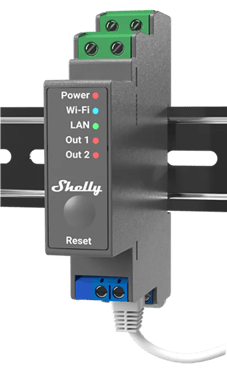 | The Shelly Pro 2PM does not provide the same dry-contact output and can introduce voltage to the barrier control circuit. **Using it with this wiring configuration may damage the barrier control board**. 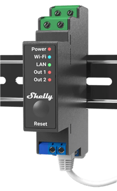 |
#### **1.2. Teltonika-RUT200 Router**
A managed cellular router that gives the Shelly a secure internet connection over the mobile network (no site broadband needed). NOTE: If customer ethernet is available at the barrier, this device is not required

You are wiring these two devices in and providing power and a network link. **Ronspot handles all the software/onboarding remotely** so you don't configure any apps or accounts.
**This does not replace or alter the barrier.** The Shelly sits alongside the existing controls and injects no voltage into the barrier. Any other access system on the barrier (e.g. an ANPR camera) keeps working exactly as before — see Shared / multi-tenant barriers below.
### 2. How it works (in one minute)
`User with a booking ➡️ Ronspot app ➡️ Ronspot cloud ➡️ 4G (mobile network) ➡️ Teltonika Router ➡️ Ethernet (PORT LAN) ➡️ Shelly Pro 2 ➡️ volt-free contact ➡️ barrier controller "open" input ➡️ barrier opens`
An “open” from Ronspot travels down the mobile network to the Teltonika router, into the Shelly over its Ethernet cable, and the Shelly briefly closes a dry contact (~2 seconds) wired across the barrier's open command. The barrier opens and auto-closes on its own timer, just as it does today.
### 3. Before you begin
- **This is mains-adjacent, safety-critical work for a qualified electrician**, in line with local wiring regulations. On a barrier that also serves other tenants, it should be done by (or agreed with) the barrier's own approved installer, with the building/site manager's sign-off.
- **Isolate the supply and prove dead** before wiring.
- Have the **barrier controller's manual** to hand as it is the authority on which terminal is the “open” input and what type it is.
- **Confirm every terminal against the printed labels** on the Shelly and the barrier controller before energising. Silkscreen can vary by revision — the label on the unit wins over this guide.
### 4. What's in the kit
| Item | Notes |
| --- | --- |
| **Shelly Pro 2 V1** | 2-channel DIN-rail relay, potential-free / dry contacts. Mains powered (110–240 V AC). Supplied without plug or lead. |
| **Teltonika Router** | Pre-provisioned by Teltonika. Ships with power supply, aerial(s) and a wall bracket. Wi-Fi is disabled. |
| **Ethernet patch lead** | Links the Shelly to the Teltonika router. |
### 5. How to configure GateLIFT
#### Step 1: Mount the devices
Mount both inside the barrier's control enclosure (or a suitable adjacent lockable enclosure):
1. The Shelly Pro 2 clips onto DIN rail. Keep it dry and within −20 to +40 °C.
2. The Teltonika router fits on its click-in wall bracket. Position it so the aerial has a clear path to the outside for good signal — avoid burying it inside a metal cabinet if signal is weak.
3. Leave the Ethernet lead accessible between the two.
---
#### Step 2: Set up the Teltonika router
The router is **pre-configured and sealed by Teltonika**, there is nothing to log into.
1. Fit the aerial(s) (hand-tight).
2. Connect the supplied power supply (the router runs on low-voltage DC — use the unit provided; do not substitute).
3. Power on and wait 1–2 minutes for it to register on the mobile network. Confirm the signal/status LEDs show a connection (see the router's quick-start label).
**TIP:** If the status LEDs indicate poor or no signal, reposition the aerial toward a window/opening or use an external aerial. The router needs a working mobile signal at the barrier location. If signal strength remains an issue a longer antenna will be required.
---
#### Step 3: Connect the Shelly to the router
Patch the Shelly's LAN (RJ45) port to the Teltonika router with the Ethernet lead.
**IMPORTANT: Use PORT LAN.** The Teltonika router has two Ethernet ports, LAN and WAN. The Shelly must be plugged into PORT LAN. It will not work on port WAN.
---
#### Step 4: Power the Shelly (mains)
Wire a 110–240 V AC supply to the Shelly's supply terminals:
- **Line → `L`**
- **Neutral → `N`**
- Protect the supply with an appropriately rated **MCB/fuse** per local regs.
- **Leave `SW1` and `SW2` unconnected**: the Shelly is triggered over the network, not by a local switch.
**Check:** on power-up the Shelly's power LED lights, and (from Step 3) it links to the router.
---
#### Step 5: Wire the barrier “open” contact *(the key connection)*
The barrier is opened by **Relay 1's volt-free contact — terminals `O1` and `I1`.**
1. Wire **`O1`** and **`I1`** to the barrier controller's **“open command” / “remote open” / “key-switch” input**, **in parallel** with the existing open control (button, fob receiver, ANPR relay, intercom, etc.).
2. This is a **normally-open, volt-free (dry) contact.** It carries **no voltage** — it simply closes the circuit the same way the open button does. **Polarity doesn't matter.**
3. When triggered, Ronspot closes it for a **momentary pulse (~2 s)**, then it releases automatically. The pulse length is set by Ronspot — nothing to set on site.
- **Confirm in the barrier manual** that this input is a volt-free trigger. *(Example: CAME control boards use a normally-open contact across the “open” terminals — e.g. `2–3` on many boards.)* If the controller expects a specific signal or voltage instead, **stop and consult Ronspot,** do not improvise.
- **Do not change the barrier controller's settings** (DIP switches, jumpers, timers). You are only adding a parallel trigger, leave the board configured as it is for the existing system.
---
#### Step 6: Optional second contact (hold-open / exit / second barrier)
**Relay 2 (`O2` / `I2`)** is a second independent volt-free contact. Wire it only if required:
- **Hold-open (maintenance).** To hold the barrier **fully open** and later release it, wire `O2`/`I2` to the controller's **dedicated hold-open input** (labelled *hold-open / permanent-open / free-passage / day-mode*). **Do NOT use the momentary “open” input for this** — holding that closed does not reliably keep the barrier up (most controllers still auto-close). Confirm whether that input is **maintained** or **toggle**, and tell Ronspot.
- **Exit / second barrier.** Wire `O2`/`I2` (momentary) to that barrier's open input, same as Step 5.
Skip this step if only a single “open” is required.
---
#### Step 7: Commission and test (with Ronspot)
1. Confirm the Shelly's power LED is on and it's connected to the router.
2. Ronspot confirms the controller shows **Online** in the admin panel, then sends a **Test open**.
3. Confirm: the Shelly relay **clicks** and its output LED lights for ~2 s, **and the barrier opens** and auto-closes as normal.
4. If Step 6 was wired, test that function too.
### 6. Shared / multi-tenant barriers
On a barrier shared with other tenants (e.g. an existing ANPR camera system), the two systems run independently and in parallel:
- Both are just normally-open dry contacts across the same open input — either can open the barrier, neither can block the other.
- If the Shelly loses power or the mobile link drops, its contact simply sits open — the existing system is completely unaffected, and vice-versa.
- Because the Shelly contact is potential-free, there's no back-feed between the systems — they stay electrically isolated.
- One caveat: it's still one physical barrier, so a hold-open raises it for everyone, not just Ronspot users.
### 7. Do NOT
- Apply mains or any voltage to the `O1/I1` (or `O2/I2`) barrier-contact terminals.
- Plug the Shelly into the router's **port WAN** (use **port LAN**).
- Use `SW1` / `SW2` (leave them unconnected).
- Reconfigure the barrier controller (DIPs, jumpers, timers) or remove/bypass any safety device (loops, photocells, edges).
- Substitute the Teltonika router's power supply.
### 8. Troubleshooting
| Symptom | Check |
| --- | --- |
| **Controller shows Offline in Ronspot** | Router powered and showing signal LEDs? Shelly Ethernet in **PORT LAN** (not WAN)? Aerial fitted and getting mobile signal? |
| **Shelly relay clicks but barrier doesn't move** | `O1`/`I1` landed on the correct **open** input? Is the barrier controller powered and its existing controls working? Any safety device holding it? |
| **Nothing happens on Test open** | Shelly power LED on? Ethernet link light on **port LAN**? Ask Ronspot to confirm the device is online. |
| **Barrier opens but won't stay up for maintenance** | Hold-open must be on the controller's **dedicated hold-open input** (Step 6), not the momentary open input. |
| **Weak/no mobile signal** | Reposition or fit an external aerial; the router needs signal at the barrier location. |
### 9. Sign-off checklist
- Supply isolated during work; correct MCB/fuse fitted.
- Teltonika router powered (supplied PSU), aerial fitted, signal LEDs OK.
- Shelly Ethernet patched to Teltonika router **PORT LAN**.
- Shelly `L`/`N` wired; power LED on; `SW1`/`SW2` empty.
- `O1`/`I1` wired to the barrier's **volt-free open input, in parallel** with existing controls.
- (If required) `O2`/`I2` wired to the second function.
- **Test open** verified: relay clicks + barrier opens + auto-closes.
- Existing barrier controls/safety devices untouched and working.
### 10. Reference
- [**Shelly Pro 2 V1**](https://help.ronspot.co/hubfs/shelly-pro-2-user-manual.pdf?hsLang=en): manufacturer datasheet/[user guide](https://help.ronspot.co/hubfs/Shelly-Pro-2-Specifications.pdf?hsLang=en) (definitive terminal layout and ratings).
- [**Teltonika route**](https://wiki.teltonika-networks.com/view/RUT200_Manual)r**:** quick-start/datasheet (definitive LEDs, ports, power).
- **Barrier controller manual:** definitive “open input” terminal and type.
Where this guide differs from the manufacturer manuals or the printed terminal labels, the manuals and labels win.
**Need help configuring GateLIFT? Contact the [Ronspot support](https://ronspotflexwork.com/contact-us/customer-support/) team.**
- [User Guide](https://help.ronspot.co/user-guide?hsLang=en#main-content)
- [Quick Start](https://help.ronspot.co/user-guide?hsLang=en#quick-start)
- [Core Features](https://help.ronspot.co/user-guide?hsLang=en#core-features)
- [Advanced Features](https://help.ronspot.co/user-guide?hsLang=en#advanced-features)
- [Meetings](https://help.ronspot.co/user-guide?hsLang=en#meetings)
- [Troubleshooting](https://help.ronspot.co/user-guide?hsLang=en#troubleshooting)
- [Account Setup](https://help.ronspot.co/account-setup?hsLang=en#main-content)
- [Map Configuration](https://help.ronspot.co/account-setup?hsLang=en#map-configuration)
- [Space Management](https://help.ronspot.co/account-setup?hsLang=en#space-management)
- [Account Customisation](https://help.ronspot.co/account-setup?hsLang=en#account-customisation)
- [User Management](https://help.ronspot.co/user-management?hsLang=en#main-content)
- [User Authentication](https://help.ronspot.co/user-management?hsLang=en#user-authentication)
- [Managing Users](https://help.ronspot.co/user-management?hsLang=en#managing-users)
- [User Permissions](https://help.ronspot.co/user-management?hsLang=en#user-permissions)
- [Rules & Priorities](https://help.ronspot.co/rules-priorities?hsLang=en#main-content)
- [Confirmation & Auto-Cancellation](https://help.ronspot.co/rules-priorities?hsLang=en#confirmation-auto-cancellation)
- [Demand Management](https://help.ronspot.co/rules-priorities?hsLang=en#demand-management)
- [Priorities & Restrictions](https://help.ronspot.co/rules-priorities?hsLang=en#priorities-restrictions)
- [Integrations](https://help.ronspot.co/integrations?hsLang=en#main-content)
- [Single Sign-On](https://help.ronspot.co/integrations?hsLang=en#single-sign-on)
- [HR Systems](https://help.ronspot.co/integrations?hsLang=en#hr-systems)
- [Meeting Sync](https://help.ronspot.co/integrations?hsLang=en#meeting-sync)
- [Access Control Systems](https://help.ronspot.co/integrations?hsLang=en#access-control-systems)
- [Workplace Sensors](https://help.ronspot.co/integrations?hsLang=en#workplace-sensors)
[](https://ronspotflexwork.com/)
Download the user guide
**[Parking user guide](https://ronspotflexwork.com/ronspot-parking-user-guide-en.pdf)[Desk user guide](https://ronspotflexwork.com/ronspot-desk-user-guide-en.pdf) [M](https://ronspotflexwork.com/ronspot-meeting-user-guide-en.pdf)[eeting user guide](https://ronspotflexwork.com/ronspot-meeting-user-guide-en.pdf)**
Download the app
[](https://apps.apple.com/ie/app/ronspot-desk-parking-mgt/id1290760801) [](https://play.google.com/store/apps/details?id=ie.jemstone.ronspot&hl=en)
Ronspot Ltd, ATU iHubs, Dublin Road, Galway, H91 DCH9, Ireland — Ronspot® is a registered trademark. Copyright © 2025 Ronspot Ltd. All Rights Reserved.